上一章中完成了对图形渲染的饿BVH加速,现在我们要尝试将图片纹理映射到物体中。
纹理映射
图形学中的纹理映射是将材质效果应用于场景中的物理过程。其中”纹理”指的是效果(这个效果可以是材质属性,或是部分存在与否)本身,而映射则是将效果映射到物体的表面上。
最为常见的纹理映射就是将图像映射到物体表面上,就像是把世界地图依附到球体表面。和我们的直觉不同,纹理映射是一个逆向的过程,我们首先确定物体上的一个点,然后查找纹理贴图给定的颜色,以实现对图片的映射。
不过在此之前,我们先用程序化的方式生成纹理颜色,并创建一个纹理贴图。为了执行纹理查找,我们需要物体表面的纹理坐标(u,v)以定位纹理中的像素,同时也需要保存当前点的三维坐标(部分纹理需要这一部分的信息)
恒定色彩纹理
我们的纹理颜色类将从最简单的恒定色彩纹理开始实现,实际上我们可以将物体的颜色也视作一种纹理:
1 2 3 4 5 6 7 8 9 10 11 12 13 14 15 16 17 18 19 20 21 22 23 24 #ifndef TEXTURE_H #define TEXTURE_H #include "utils.h" class texture { public : virtual ~texture () = default ; virtual color value (double u, double v, point3& p) const 0 ; }; class solid_color : public texture{ public : solid_color (const color& albedo) : albedo (albedo) {} solid_color (double red, double green, double blue) : solid_color (color (red,green,blue)) {} color value (double u, double v, point3& p) { return albedo; } private : color albedo; }; #endif
这里我们先实现对纹理类的接口的一个实现,然后创建一个恒定色彩纹理类,返回恒定的颜色类型。
注意到我们这里需要使用到(u,v)表面坐标,我们还需要更新hit_record结构,对这些射线碰撞信息进行存储:
1
2
3
4
5
6
7
8
class hit_record {public : point3 p; double u; double v; vec3 normal; ... };
棋盘纹理
棋盘纹理作为实体纹理中的一种。实体纹理取决点在空间中的位置,我们可以理解为给空间中的指定点进行着色,而不是给空间中的某个物体上色。正因如此,当我们的物体在空间中移动时,纹理并不会随物体进行移动,反而像是物体在穿过纹理。
这里我们将实现一个棋盘纹理类,它是一种空间纹理(即实体纹理)。根据点在空间中给定的位置进行纹理颜色的渲染。
为了实现棋盘格图案,我们需要对当前点的每个坐标分量取floor,这样我们就将整个空间分割为1x1x1的单元格,每个坐标都可以映射到对应的单元格,我们对奇数的单元格赋予一种颜色,对偶数赋予另外的一种颜色,这样就实现了棋盘的样式。同时我们还可以设置一个缩放因子scale,控制单元格的大小,从而实现对棋盘格的大小控制:
1
2
3
4
5
6
7
8
9
10
11
12
13
14
15
16
17
18
19
20
21
22
23
class checker_texture : public texture{ public : checker_texture (double scale, shared_ptr<texture> even, shared_ptr<texture> odd) : inv_scale (1.0 /scale), even (even), odd (odd) {} checker_texture (double scale, const color& c1, const color& c2) : checker_texture (scale, make_shared <solid_color>(c1), make_shared <solid_color>(c2)) {} color value (double u, double v, point3& p) const override { auto xInt = int (floor (inv_scale*p.x ())); auto yInt = int (floor (inv_scale*p.y ())); auto zInt = int (floor (inv_scale*p.z ())); bool isEven = (xInt + yInt + zInt) % 2 == 0 ; return isEven ? even->value (u,v,p) : odd->value (u,v,p); } private : double inv_scale; shared_ptr<texture> even; shared_ptr<texture> odd; };
为了进一步的支持纹理,我们拓展lambertian类,使用纹理代替颜色:
1
2
3
4
5
6
7
8
9
10
11
12
13
14
15
16
17
18
19
20
21
class lambertian : public material {public : lambertian (const color& albedo) : tex (make_shared <solid_color>(albedo)) {} lambertian (shared_ptr<texture> tex) : tex (tex) {} virtual bool scatter ( const ray& r_in, const hit_record& rec, color& attenuation, ray& scattered ) override auto scatter_direction = rec.normal + random_unit_vector (); if (scatter_direction.near_zero ()) { scatter_direction = rec.normal; } scattered = ray (rec.p, scatter_direction, r_in.time ()); attenuation = tex->value (rec.u, rec.v, rec.p); return true ; } private : shared_ptr<texture> tex; };
这里通过多态的思想实现了对lambertian材质的纹理的实现。
现在我们可以向我们的场景中添加纹理了:
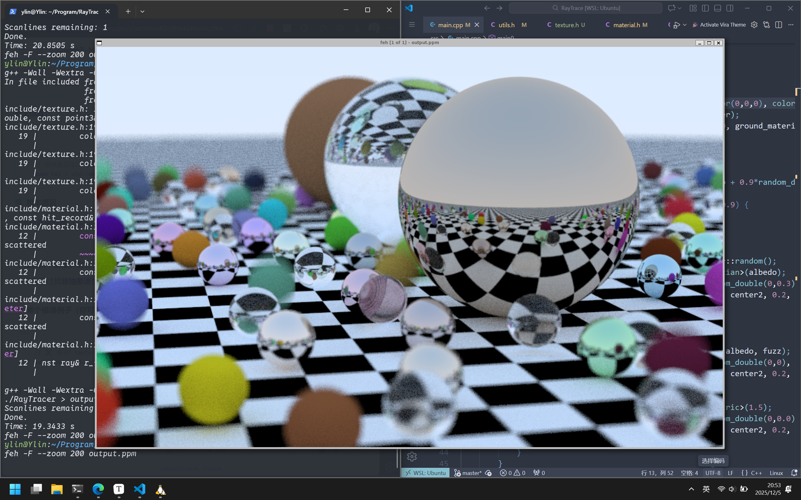
1 2 3 4 auto checker = make_shared <checker_texture>(0.2 , color (0 ,0 ,0 ), color (1 ,1 ,1 )); auto ground_material = make_shared <lambertian>(checker); world.add (make_shared <sphere>(point3 (0 ,-1000 ,0 ), 1000 , ground_material));
渲染结果如下:
image.png
空间纹理的特殊情况
正如之前所提到的,这种实体纹理的上色方式,更像是物体在穿过纹理,从而完成上色。
我们现在创建一个新的场景来观察这种特殊的情况,我们将先前的main函数保存为一个bounding_ball场景,然后现在我们再来创建一个新的场景:
1
2
3
4
5
6
7
8
9
10
11
12
13
14
15
16
17
18
19
20
21
22
23
24
void checkered_spheres () hittable_list world; auto checker = make_shared <checker_texture>(0.32 , color (.2 , .3 , .1 ), color (.9 , .9 , .9 )); world.add (make_shared <sphere>(point3 (0 ,-10 , 0 ), 10 , make_shared <lambertian>(checker))); world.add (make_shared <sphere>(point3 (0 , 10 , 0 ), 10 , make_shared <lambertian>(checker))); camera cam; cam.aspect_ratio = 25.0 / 16.0 ; cam.image_width = 800 ; cam.samples_per_pixel = 100 ; cam.max_depth = 50 ; cam.vfov = 20 ; cam.lookfrom = point3 (13 ,2 ,3 ); cam.lookat = point3 (0 ,0 ,0 ); cam.vup = vec3 (0 ,1 ,0 ); cam.defocus_angle = 0 ; cam.render (world); }
我们通过main函数中的switch来切换我们想要渲染的场景:
1
2
3
4
5
6
int main () { switch (2 ){ case 1 : bounding_ball(); break ; case 2 : checkered_spheres(); break ; } }
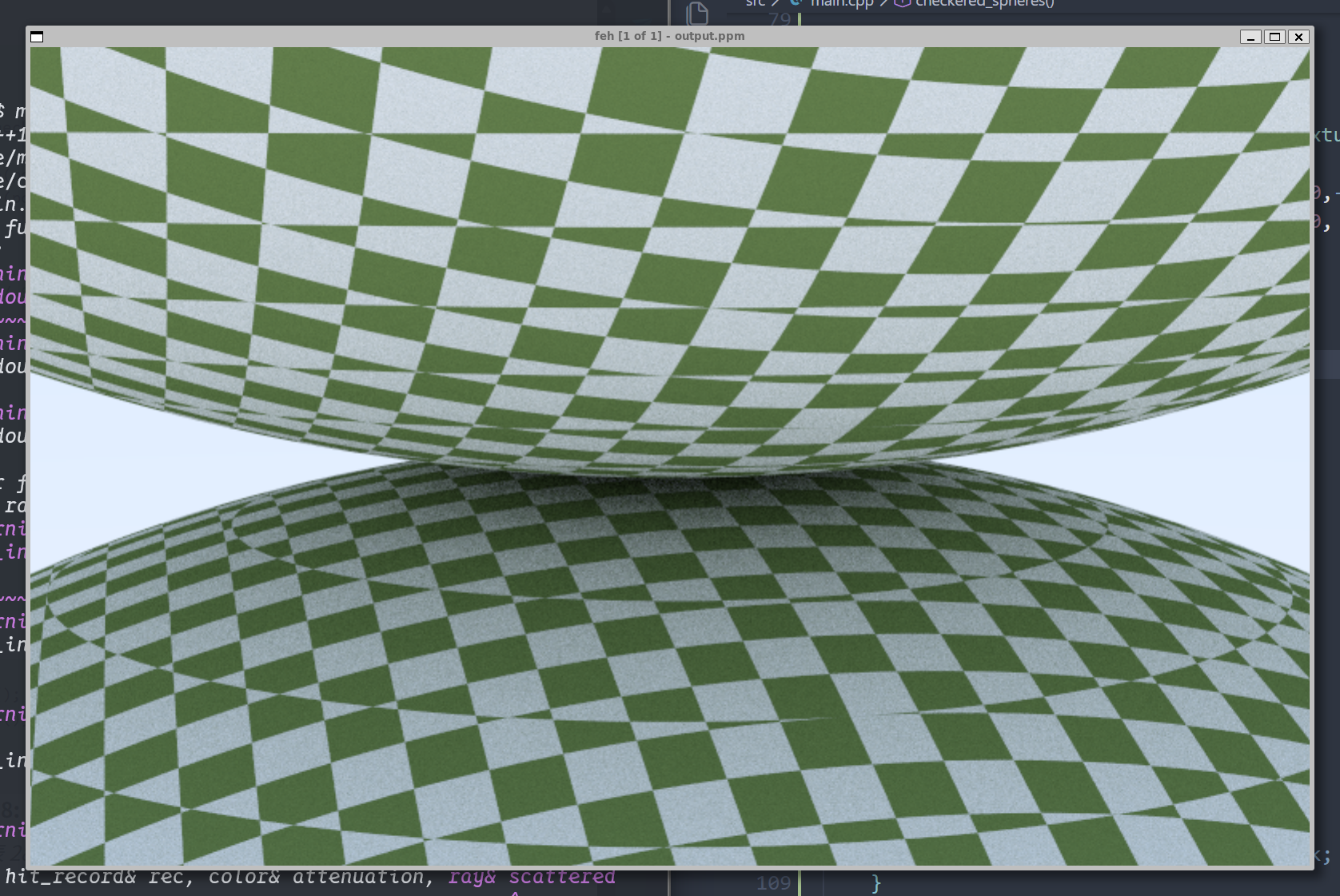
我们渲染出来的结果如下:
image.png
这就是空间纹理渲染的特殊情况,不过你应该能理解这是什么情况。所以为了解决这个问题,我们需要使用表面纹理,这就意味着我们需要根据(u,v)的球体表面位置信息来创建纹理。
球体表面纹理坐标
空间纹理通过空间中一点的坐标,实现纹理的绘制。但是真如我们先前所提到的空间纹理的局限性,我们希望能够更具球体表面的坐标实现对图像点对点的映射。这就以为着我们需要一种方法来查找三维球体表面任意点的坐标(u,v)。
这里用到一个经纬度的思想,首先确定出这个点在球体上的经纬度(θ , ϕ ) (横纬竖经,这里θ ϕ 我 们 可 以 简 单 的 推 导 得 到 :sphere类中的get_uv方法:
1
2
3
4
5
6
static void get_uv (const point3& p, double & u, double & v) auto theta = std::acos (-p.y ()); auto phi = std::atan2 (-p.z (),p.x ()) + pi; u = phi / (2 *pi); v = theta / pi; }
然后我们向hit方法中添加,每次碰撞记录的(u,v):
1
2
3
4
5
6
7
8
9
10
11
bool hit (const ray& r, interval t_range, hit_record& rec) const override ... rec.t = root; rec.p = r.at (rec.t); vec3 outward_normal = (rec.p - cur_center) / radius; rec.set_face_normal (r, outward_normal); get_uv (outward_normal,rec.u,rec.v); rec.mat = mat; return true ; }
现在我们就实现了对球体表面的位置的(u,v)二维定位
访问纹理图像数据
现在我们需要一种手段,将图片数据解析为一种二维关系,我们希望通过(u,v)访问图像数据上对应的像素值。所以我们需要将图片加载为一个浮点数数组,便于我们访问。这里我们使用第三方库stb_image.h来实现
首先我们创建一个辅助类来帮助我们管理图片信息内容,以提供一个pixel_data(int x,int y)方法,来访问任意像素的8位(unsigned
char)RGB。
我们的实现如下:
1 2 3 4 5 6 7 8 9 10 11 12 13 14 15 16 17 18 19 20 21 22 23 24 25 26 27 28 29 30 31 32 33 34 35 36 37 38 39 40 41 42 43 44 45 46 47 48 49 50 51 52 53 54 55 56 57 58 59 60 61 62 63 64 65 66 67 68 69 70 71 72 73 74 75 76 77 78 79 80 81 82 83 84 85 86 87 88 89 90 91 92 #ifndef IMAGE_H #define IMAGE_H #ifdef _MSC_VER #pragma warning (push,0) #endif #define STB_IMAGE_IMPLEMENTATION #define STBI_FAILURE_USERMSG #include "stb_image.h" #include "utils.h" class image { public : image (){} image (const char * image_file){ auto filename = std::string (image_file); if (load ("../images/" + filename)) return ; std::cerr << "ERROR: Could not load image file" << image_file << "\n" ; } ~image (){ delete [] bdata; STBI_FREE (fdata); } bool load (const std::string& filename) auto n = bytes_per_pixel; fdata = stbi_loadf (filename.c_str (), &image_width, &image_height, &n, bytes_per_pixel); if (fdata == nullptr ) return false ; byte_per_scanline = bytes_per_pixel * image_width; convert_to_bytes (); return true ; } int width () return (fdata==nullptr ) ? 0 : image_width;} int height () return (fdata==nullptr ) ? 0 : image_height;} const unsigned char * pixel_data (int x, int y) const static unsigned char magenta[] = {255 ,0 ,255 }; if (bdata==nullptr ) return magenta; x = clamp (x,0 ,image_width); y = clamp (y,0 ,image_height); return bdata + x*bytes_per_pixel + y*byte_per_scanline; } private : const int bytes_per_pixel = 3 ; float * fdata = nullptr ; unsigned char * bdata = nullptr ; int image_width = 0 ; int image_height = 0 ; int byte_per_scanline = 0 ; static int clamp (int x, int low, int high) if (x < low) return low; if (x < high) return x; return high - 1 ; } static unsigned char float_to_byte (float value) if (value <= 0.0 ) return 0 ; if (value >= 1.0 ) return 255 ; return static_cast <unsigned >(value*256.0 ); } void convert_to_bytes () int total_bytes = bytes_per_pixel * image_height * image_width; bdata = new unsigned char [total_bytes]; auto *bptr = bdata; auto *fptr = fdata; for (auto i=0 ; i<total_bytes ; i++,fptr++,bptr++) *bptr = float_to_byte (*fptr); } }; #ifdef _MSC_VER #pragma warning (pop) #endif #endif
现在我们封装好了一个加载并获取图像内容的image类,我们可以利用它实现图像纹理image_texture:
1
2
3
4
5
6
7
8
9
10
11
12
13
14
15
16
17
18
19
20
21
22
23
24
class image_texture : public texture{ public : image_texture (const char * filename) : image (filename){} color value (double u, double v, const point3& p) const override { if (image.height () <= 0 ) return color (0 ,1 ,1 ); u = interval (0 ,1 ).clamp (u); v = 1.0 - interval (0 ,1 ).clamp (v); auto i = int (u*image.width ()); auto j = int (v*image.height ()); auto pixel = image.pixel_data (i,j); auto color_scale = 1.0 / 255.0 ; return color (color_scale*pixel[0 ], color_scale*pixel[1 ], color_scale*pixel[2 ]); } private : image image; };
图像纹理渲染
现在我们可以尝试将一个图片进行渲染:
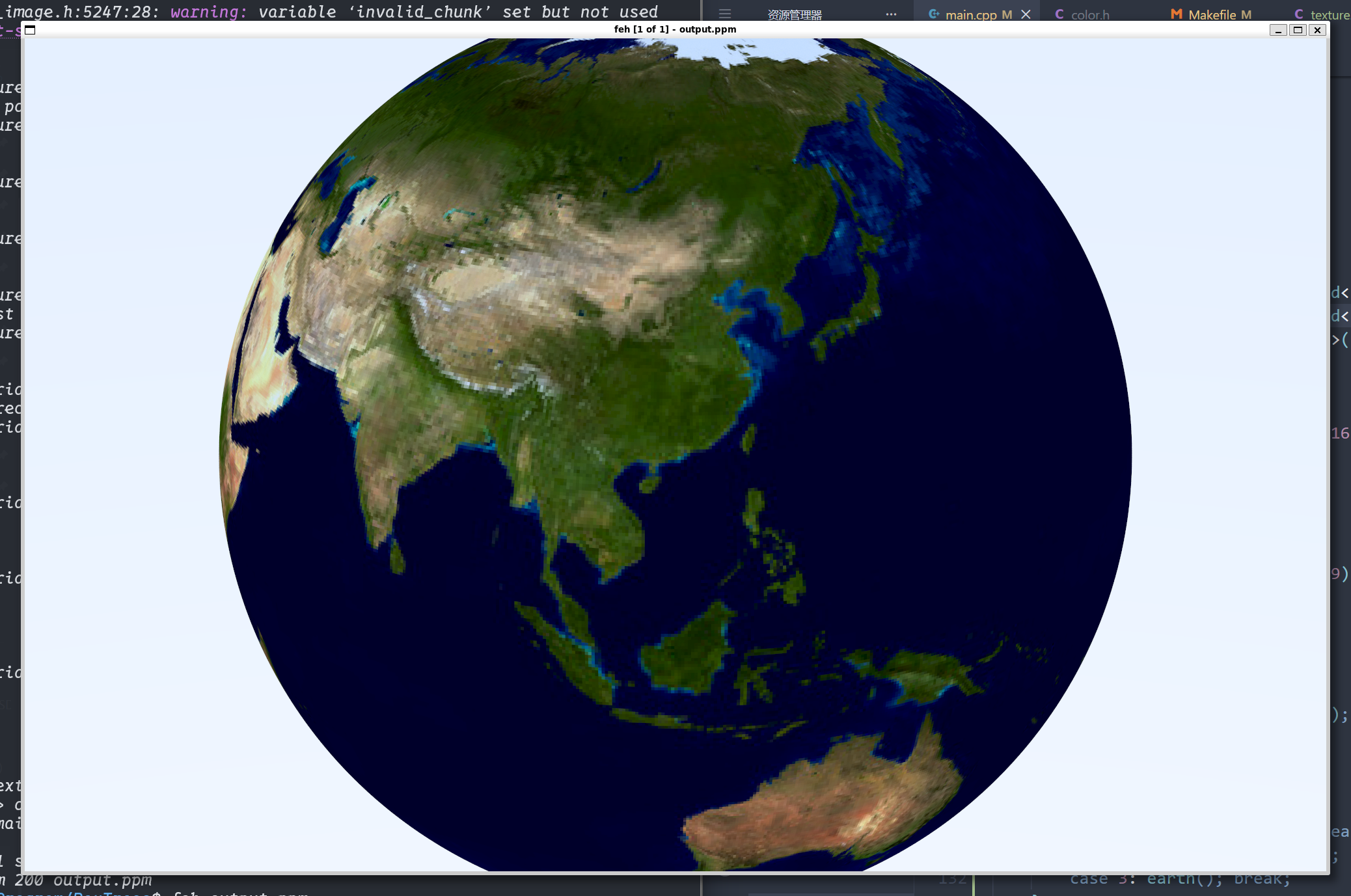
1
2
3
4
5
6
7
8
9
10
11
12
13
14
15
16
17
18
19
20
21
void earth () auto earth_texture = make_shared <image_texture>("earthmap.jpg" ); auto earth_surface = make_shared <lambertian>(earth_texture); auto globe = make_shared <sphere>(point3 (0 ,0 ,0 ), 2 , earth_surface); camera cam; cam.aspect_ratio = 25.0 / 16.0 ; cam.image_width = 2000 ; cam.samples_per_pixel = 100 ; cam.max_depth = 10 ; cam.vfov = 20 ; cam.lookfrom = point3 (-3.75 ,4 ,-9 ); cam.lookat = point3 (0 ,0 ,0 ); cam.vup = vec3 (0 ,1 ,0 ); cam.defocus_angle = 0 ; cam.render (hittable_list (globe)); }
我们使用一张地球的贴图(效果如下):
image.png
至此 我们的纹理样式就简单介绍完了