0%

29:初始图形学(3)

昨天休息了一天,今天继续图形学的学习

向场景发射光线

现在我们我们准备做一个光线追踪器。其核心在于,光线追踪程序通过每个像素发送光线。这意味着对于图像中的每个像素点,程序都会计算一天从观察者出发,穿过该像素的光线。并且计算这个光线的方向上所看到的像素的颜色。其步骤为以下几点:

  • 计算从“眼睛”发出的通过像素的光线
  • 确定光线与物体的交汇
  • 计算交点像素的颜色和性质

设置一个摄像机

除了设置渲染图像的像素维度,我们还需要一个虚拟视口,通过这个视口传递场景光线。这个视口是3D世界中的一个虚拟矩形,其中包含图像像素网格的位置。如果像素在水平方向和垂直方向上的距离相同(正方形像素),那么用于生成这些像素的视口也将具有具有相同的渲染比例。两个相近的像素之间的距离称之为像素间距,通常被单位化,用于计算。

首先我们随意设置一个为2的视口高度,并将视口宽度缩放,以获得我们需要的宽高比例,下面是渲染图像的设置:

1
2
3
4
5
6
7
8
9
10
auto aspect_radio = 16.0/9.0;	//长宽比
int image_width = 400;

//计算图像的高度,并确保图像的高度至少为1(单位长度)
int image_height = int (image_width / aspect_radio);
image_height = (image_height < 1) ? 1 : image_height;

//确保视口的宽高比和图像的宽高比一样
auto viewport_height = 2.0;
auto viewport_width = viewport_height * (double(image_width)/image_height);

这里之所以没有使用aspect_radio来计算视口宽度是因为,为了确保其比例更加的真实。因为aspect_ratio是一个理想的比例,但是并不真实。图像的宽高比可能会在四舍五入的过程中丢失精度,所以此时的aspect_ratio并不准确,要得到真正的宽高比,我们直接使用图像的宽高比来进行计算。

接下里我们需要定义摄像机的中心:一个3D空间中的点,所有的场景光线都将从这个点出发(这个点通常也被称之为视点)。从相机中心到视口中心的向量将与视口垂直。我们将视口到视点的距离看作一个单位。这个距离我们称其为焦距。

我们可以通过这张图理解视点和视口的关系,但是忽略图上的方向,我们只需要知道Z轴是从视点指向视口的方向即可

image.png

实际上我们将视口的左上角定为(0,0),然后扫描像素时从左上角开始,逐行从左到右扫描,然后逐行从上往下扫描。为了方便导航像素网格,我们设置从左往右的向量u⃗和从上往下的向量v⃗ 。然后我们根据像素间距,将像素视口均匀的分成了高x宽网格空间

image.png

下面我们写一个实现相机的代码,我们创建一个函数ray_color(const ray& r),它返回给定场景中的射线的颜色——我们先设置为总返回黑色。

1
2
3
4
5
6
7
8
9
10
11
12
13
14
15
16
17
18
19
20
21
22
23
24
25
26
27
28
29
30
31
32
33
34
35
36
37
38
39
40
41
42
43
44
45
46
47
48
49
50
#include "color.h"
#include "vec3.h"
#include "ray.h"

#include <iostream>

color ray_color(const ray& r){
return {0,0,0};
}

int main(){
auto aspect_radio = 16.0/9.0; //长宽比
int image_width = 400;

//计算图像的高度,并确保图像的高度至少为1(单位长度)
int image_height = int (image_width / aspect_radio);
image_height = (image_height < 1) ? 1 : image_height;

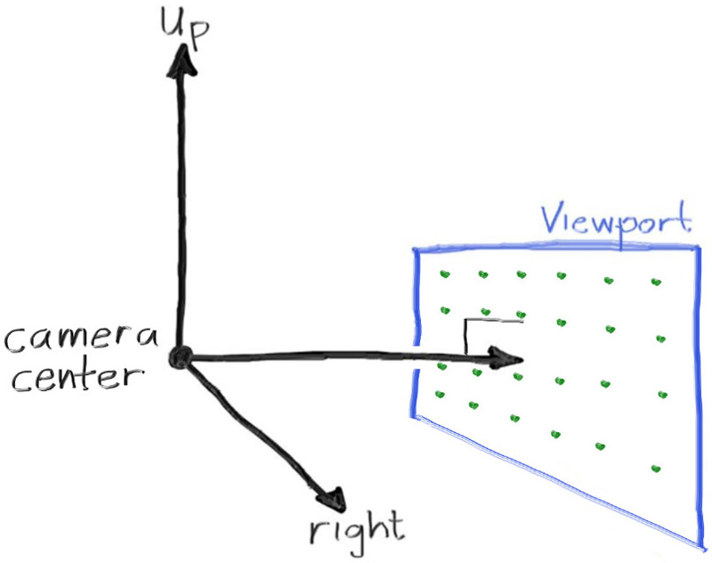
//确保视口的宽高比和图像的宽高比一样
auto focal_length = 1.0;
auto viewport_height = 2.0;
auto viewport_width = viewport_height * (double(image_width)/image_height);
auto camera_center = point3(0,0,0);

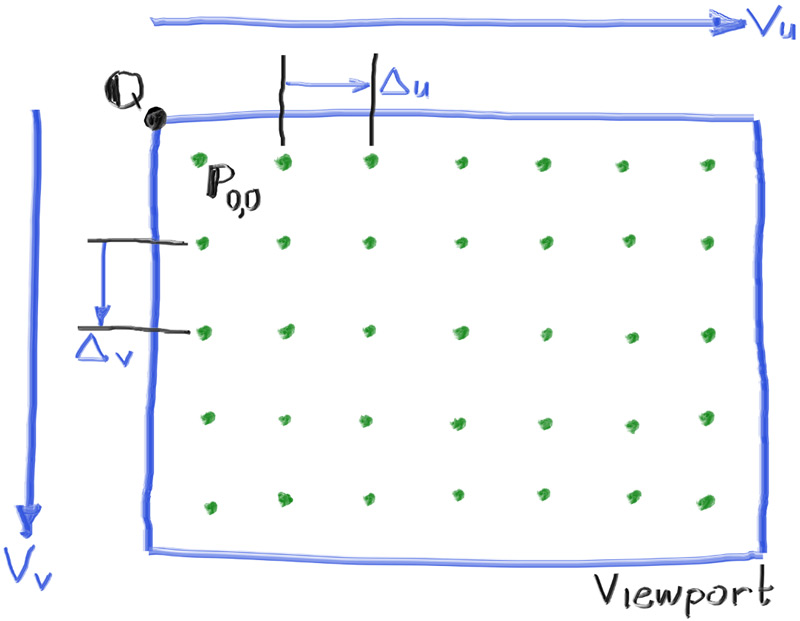
//设置视口向量与单位长度
auto viewport_u = vec3(viewport_width,0,0);
auto viewport_v = vec3(0,-viewport_height,0);
auto pixel_delta_u = viewport_u/image_width;
auto pixel_delta_v = viewport_v/image_height;

//计算像素点位
auto viewport_upper_left = camera_center - vec3(0,0,focal_length) - viewport_v/2 - viewport_u/2;
auto pixel00_loc = viewport_upper_left + 0.5*(pixel_delta_u+pixel_delta_v);


//渲染器
std::cout << "P3\n" << image_width << " " << image_height << "\n255\n";
for(int j=0;j<image_height;j++){
std::clog << "\rScanlines remaining: " << (image_height - j) << ' ' << std::flush;
for(int i=0;i<image_width;i++){
auto pixel_center = pixel00_loc + (i*pixel_delta_u) + (j*pixel_delta_v);
auto ray_direction = pixel_center - camera_center;
ray r(camera_center,ray_direction);

color pixel_color = ray_color(r);
write_color(std::cout,pixel_color);
}
}
std::clog << "\rDone. \n";
}

以上就是一个摄像机的实现了,接下来我们用它来实现背景的渲染。

渲染背景

我们接下来想要渲染一个随y变化的由蓝变白的背景,这就需要我们修改ray_color(ray)函数,从而实现一个简单的梯度函数,这个函数将根据y值来按线性规则混合白色和蓝色。

我们使用一个标准的图形技巧来实现线性混合:

blendValue = (1 − a) * startValue + a * endValue

当a接近0时,颜色趋近为起始颜色。当a接近1时,颜色接近目标颜色。

我们修改函数ray_color(ray& r)实现这个功能:

1
2
3
4
5
color ray_color(ray & r){
vec3 unit_direction = unit_vector(r.direction());
auto a = 0.5*(unit_direction.y() + 1.0);
return (1.0-a)*color(1.0,1.0,1.0) + a*color(0.5,0.7,1.0);
}

我们编译执行,得到了渲染后的图片:

image.png

今天就先到这里啦。